This article focuses on the methods for sizing four-core and five-core cables carrying current having triplen harmonic content, and includes a practical example.
Introduction
An article in Connections magazine, issue 229, explained harmonic currents and their origins. A second article in issue 230 introduced triplen harmonic currents in a three-phase circuit and highlighted the necessity of increasing cable conductor size to accommodate such types of harmonics.When determining the required size of multi-core cables, Appendix 4 of BS 7671 provides tabulated values of current-carrying capacity based fundamentally on a balanced three-phase circuit with no harmonic content, and where the current and heating effect in the neutral conductor is zero. The current-carrying capacity of a four-core cable is therefore considered equivalent to that of a three-core cable of the same construction and conductor size.
In contrast, a current will flow in the neutral conductor of an unbalanced three-phase circuit with no harmonic content. However, this neutral current and subsequent heating effect are offset by a reduction in current flow and heating in one or more of the line conductors (523.6.2). Therefore, the current carrying capacity of the circuit is considered the same as that of a balanced three phase load.
As explained previously in Connections magazine, issue 230, triplen harmonics in the circuit current will not cancel out in the neutral. Consequently, the neutral conductor will carry current and produce heat even under balanced conditions. Additionally, if the load current is unbalanced, the current and heating effect in the neutral will be much greater. Similarly, triplen, and other harmonic currents will cause heating in the line conductors.
As would be expected, all of these heating effects will lead to a reduction in the current-carrying capacity of circuit conductors.
Sizing four and five-core cables for triplen harmonic currents
When sizing the live conductors for a four or five-core cable, with four loaded cores supplying current with triplen harmonic content to a balanced three-phase load, an additional rating factor must be applied. This factor takes into account the heat generated by the triplen harmonic currents in both the line and neutral conductors, as outlined in section 5.5 of Appendix 4.This additional rating factor supplements other applicable rating factors for the installation design, such as for ambient temperature, for grouping or for thermal insulation as detailed in Section 3 of Appendix 4.
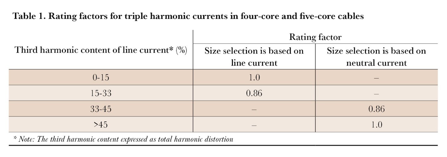
Where the neutral conductor is of the same material and cross-sectional area as that of the line conductors, the additional rating factor may be obtained from Table 4Aa of section 5.5 Appendix 4 of BS 7671, which is reproduced in Table 1.
The rating factor values given in Table 4Aa are based on the 3rd harmonic component of the line current, although they can be used where other triplen harmonics (9th, 15th, etc.) are present in the line current.
 When determining the size of a cable’s conductors using Table 1 and including any other associated rating factors, the conductor size should be selected on the basis of either the line, or the neutral current. This selection is dependent on the proportion of the 3rd harmonic content present in the line current. If the triplen harmonic content:
- Does not exceed 33 %, sizing should be based on the line current, as this current will be greater than the current in the neutral.
- Exceeds 33 %, sizing should be based on the neutral current, as this current will then be greater than the line current.
Example
A three-phase, four-wire circuit is designed to carry a load with a fundamental line current of 60 A. This circuit will be installed using a four-core armoured 90˚C thermosetting insulated cable. However, the switchgear connected to the cable is not suitable for conductors operating above 70˚C. As a result, the conductor size for the cable must be based on the current ratings for a four-core armoured 70˚C thermoplastic insulated cable (512.1.5), as provided in Table 4D4A of Appendix 4 of BS 7671.The cable is to be installed on a perforated cable tray (Reference Method E of section 7.1 of Appendix 4) alongside four other circuits (Cg = 0.75, from Table 4C1). The expected ambient temperature is 40˚C (Ca = 0.87 from Table 4B1). Overcurrent protection is to be provided by a BS EN 60898-1 circuit-breaker installed in both the line and neutral conductors.
Determine the minimum size of cable that meets the requirements of BS 7671 for current carrying capacity for each of the following four load conditions:
- A load that does not produce any 3rd harmonic content.
- A load with a 3rd harmonic current of 25 % of the fundamental current.
- A load with a 3rd harmonic content of 40 % of the fundamental current.
- A load with a 3rd harmonic content of 50 % of the fundamental current.
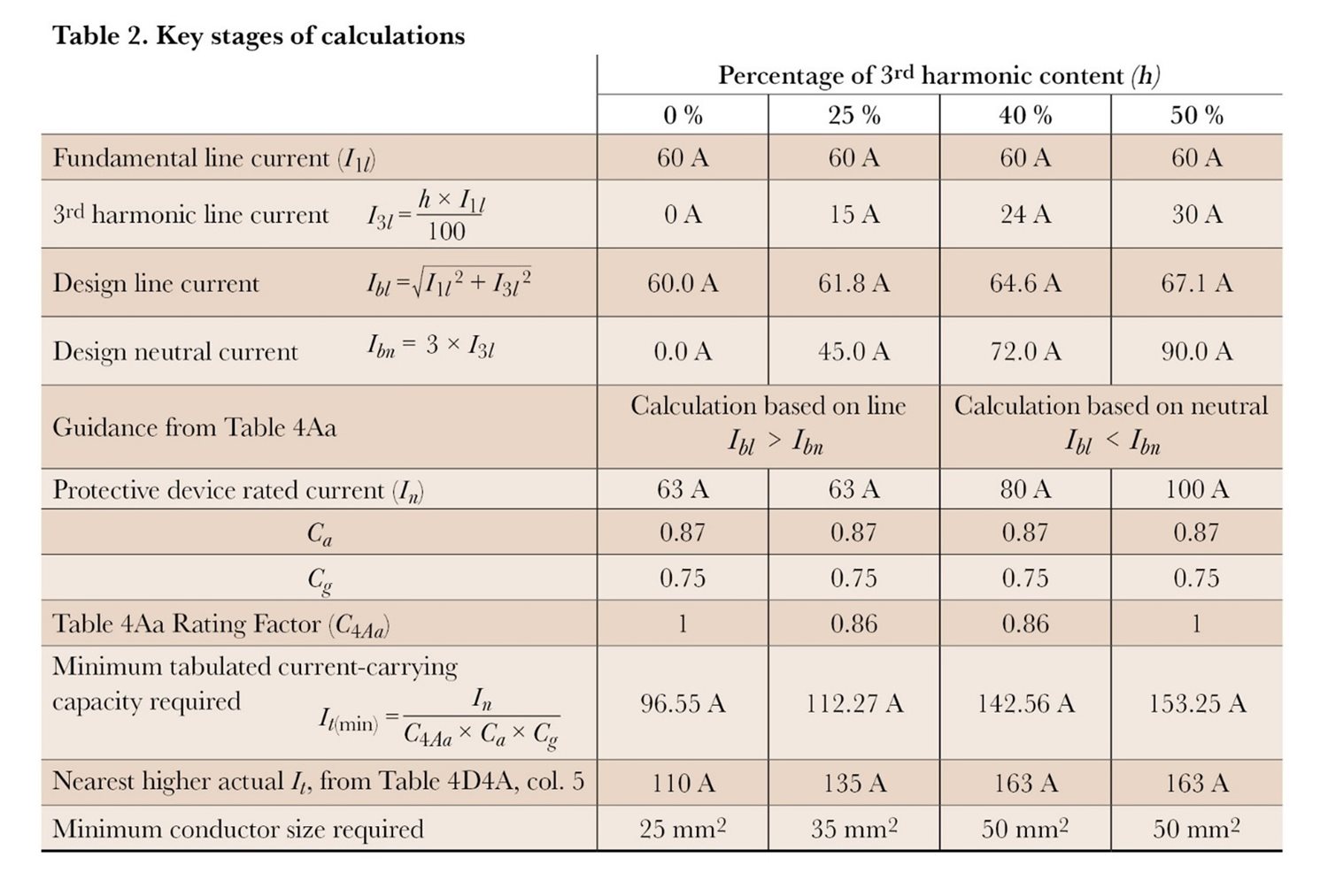
The key stages in the calculations are shown in Table 2.

From Table 2, the minimum conductor size required for a four-core cable (or a five-core cable with one core functioning as a protective conductor) is 25 mm2 where h = 0 %, 35 mm2 where h = 25 %, 50 mm2 where h = 40 %, or 50 mm2 where h = 50 %.
However, to meet the requirements for voltage drop in the circuit larger conductor sizes may be required.
When a range of harmonic currents is present
The method outlined in Section 5.5 of Appendix 4 only takes account triplen harmonic content and the resulting heating effect in both the line and neutral conductors.However, if the load characteristics result in significant levels of other harmonics (such as the 5th, 7th etc), their heating effect on the line conductor should also be considered.
Section 5.6 suggests that for cables with conductors of a cross-sectional area less than 50 mm2, the effect of other harmonic currents can be accounted for by applying a rating factor (Ch) to the fundamental design current:
Where:
I1 = 50 Hz current
I h5= 5th harmonic current
I hn = nth harmonic current
It is worth noting that Section 5.6 uses the abbreviation (If) to represent the fundamental current, but to maintain consistency with other sections of Appendix 4, the reproduced formula uses I1.
For conductor sizes of 50 mm2 and above, the increase in conductor resistance due to skin effect and proximity effect at higher harmonic frequencies will also need to be considered. This is outside the scope of this article although additional guidance on the methods for calculation can be found in BS IEC 60287-1-1.


