The aim of this article is to look at overcurrent; and in particular short-circuit current, and how the requirements of BS 7671 are applied.
Introduction
The different types of current that can lead to an overcurrent occurring in a circuit are shown in the block diagram of Fig 1.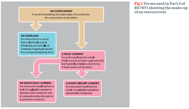
Fault current
Fault current consists of two types of fault, as shown in Fig 1 - earth faults and short-circuits.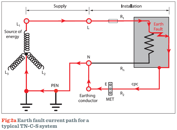
• Earth fault currents flow when there is fault between a live conductor and earth as shown in Fig 2a.
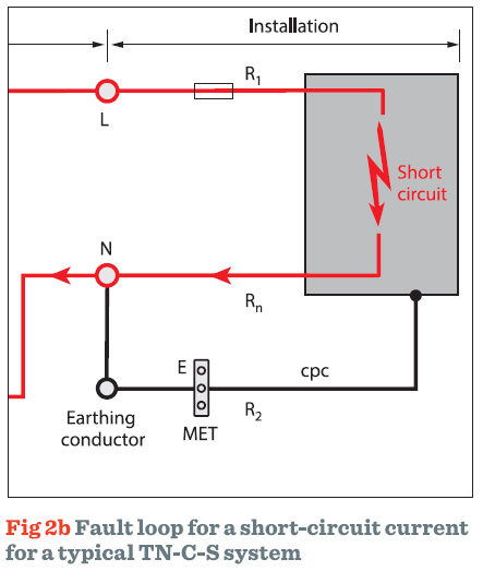
• A short-circuit current flows as a result of a fault between live conductors, for example line-to-line or line-to-neutral, as shown in Fig 2b.
The anticipated fault current in such a circuit is called the prospective fault current (Ipf).
This article will only consider shortcircuit currents between live conductors.
Short-circuit current
The short-circuit loop is indicated by the red line in Fig 2b. Because of the higher values of current typically associated with short-circuit conditions, care must be taken when selecting appropriate switchgear and protective devices.Regulation 434.5.1 requires that the rated short-circuit breaking capacity of each circuit protective device shall normally not be less than the maximum prospective fault current at the point at which the device is installed.
However, a protective device having a lower breaking capacity is permitted if another protective device having the necessary rated short-circuit breaking capacity is installed on the supply side, as shown in Fig 3. In this situation, the characteristics of the devices shall be coordinated so that the energy letthrough of these devices does not exceed that which can be withstood, without damage, by the device(s) on the load side.
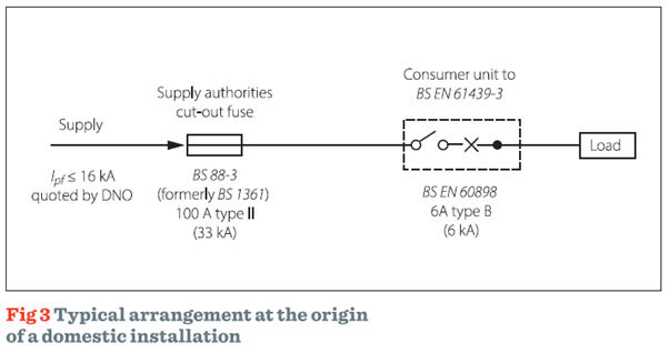
In domestic (household) or similar premises, where a consumer unit to BS EN 61439-3 is used and the maximum prospective fault current declared by the distributor is 16 kA, it is not necessary to measure or calculate prospective fault current at the origin of the supply. This specific conditional short-circuit rating applies when using an upstream BS 88-3 (formerly BS 1361 type II) fuse-link with a maximum 16 kA PSCC at the service cutout and not at the consumer unit.
The relationship between the protective device and the cable
While regulation 434.5.1 typically relates to a protective device and its ability to withstand the effects of the maximum prospective fault current, regulation 434.5.2 is concerned with limiting the heat that will be added to the current-carrying conductor while such a fault exists.For any applicable disconnection time the maximum energy withstand of the cable must be equal to or greater than the let-through energy of the protective device. Where this is not the case, there is the risk that under fault conditions the insulation may suffer thermal damage.
The time, t, in which a given fault current will raise the live conductors from the highest permissible temperature in normal duty to the limiting temperature, can, as an approximation, be calculated from the adiabatic equation given in regulation 434.5.2:
It should be remembered that an earth fault has a maximum disconnection time of 5s for TN systems (411.3.2.3). However, there is no such limitation on time given in regulation 434.5.2 for short-circuit currents. Nevertheless, a check must be made to ensure that the protective device operates before the cable becomes damaged.
Transposing the equation further to express the terms of the thermal relationship gives:
On one side is the thermal withstand of the cable k2S2 and on the other side is the let-through energy I2t of the protective device. The maximum thermal withstand of the cable depends on its cross-sectional area S, and k, which is a factor that takes account of the material properties of conductors and insulation.
As mentioned previously, the thermal withstand of the cable must be greater than or equal to the let-through energy of the protective device therefore k2S2≥I2t.
Example
To illustrate the effects of a short-circuit occurring on a cable supplying a load, and referring to Fig 4, consider a fault occurring at position B, which due to a loose connection has some additional impedance. If the total impedance of the line-neutral loop is 4 Ω, what effect will this have upon the circuit cable?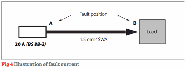
The circuit has been installed using a two-core 1.5 mm2 steel-wire armoured cable having copper conductors with 70°C thermoplastic insulation. It is protected by a BS 88-3 fuse system C fuse, rated at 20 A. Under no-fault conditions, the line-neutral loop impedance values at the supply and load can be taken as 0.28 Ω and 0.62 Ω respectively. The effects of voltage drop at the load have been ignored.
The application of the regulations of Chapter 43 shall take into account both the minimum and maximum fault current conditions; so that the highest energy let-through is considered (533.3).
Regulations 411.4.4 and 411.5.4 incorporate a voltage factor into the equations given. This voltage factor C takes account of voltage variations depending on time and place, changing of transformer taps and other considerations. The voltage factor C is not intended to take into account any fault impedance.
The values of C for a low voltage installation are given in Table 1 and are reproduced from Table 7 of PD CLC/TR 50480: 20111 Determination of crosssectional area of conductors and selection of protective devices.
Table 1 Voltage factor
Nominal voltage |
Voltage factor C | |
| Cmin | Cmax | |
| 100 V to 1,000 V | 0.95 | 1.1 |
The voltage factor used is dependent upon what is being considered. For example, when estimating maximum fault currents, Cmax is applied. When determining maximum disconnection times, Cmin is used.
The prospective fault current at position B will be:
From Fig 3A1 of BS 7671, the disconnection time for the protective device is approximately 25 seconds.
What will be the maximum time the cable can withstand this level of fault current?
Using Table 43.1, the value of k for 70 °C thermoplastic insulated copper conductors is 115
The calculations show that the cable will certainly suffer some degradation as the disconnection time exceeds the time limit at which the cable can withstand the fault current.
From Fig 3Al, the disconnection of the protective device occurs in a time less than 0.1 seconds, therefore the cable will not be exposed to damage, and the fault current is within the rated breaking capacity of the device.
The two values of prospective fault current calculated highlight the condition that the most onerous situation arises when the short-circuit current is relatively low, such as at position B.
Summary
This article has considered fault current and in particular focused on the effects of a short-circuit fault occurring between two live conductors.In the example given, the adiabatic equation was used to illustrate the effects and possible damage that may occur to a cable during a short-circuit fault. As such, for any relevant disconnection time, and to prevent thermal damage to the cable insulation during a fault, the maximum energy withstand of the cable must be equal to or greater than the let-through energy of the protective device.
Footnote
1 This published document is the UK implementation of CLC/TR 50480: 2012


