The main focus of this article is to give an introduction to overload current and how the requirements of BS 7671 are to be applied.
This will enable contractors to make an informed decision during the design stage of an installation. This will be complemented using a typical example.
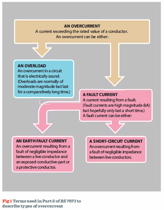
Fig 1 identifies the relationship between the different conditions that may cause an overcurrent. This article will only consider overload conditions. A subsequent article will look at short-circuit current.

However, where individual loads that are inherently not liable to overload are connected to a circuit, such as a ring final circuit, that circuit can be subjected to overload.
All circuits, whether they are liable to overload or not, must be protected against fault current, with a few exceptions (434.3).

When an overload occurs, the protective device is designed to automatically disconnect the circuit by means of the circuit-breaker tripping or fuse rupturing.
Should an overload occur in a circuit where there is no overload protection provided, the temperature of the circuit conductors is liable to increase significantly, which over time may lead to damage of insulation, joints and terminations of the conductors and/or their surroundings.
To protect against such thermal distress, any circuit design must properly coordinate the current carrying capacity of the conductors and the anticipated load current with the characteristics of the overload protective device (see Table 1).

With the exception of rewireable fuses to BS 3036, where the operating characteristics of a protective device meet the requirements of 433.1.1, as reproduced in the following expressions (i) & (ii), protection against overload will be provided:
Expression (i):
Ib ≤ In ≤ Iz
The design current of the circuit (lb) must be less than or equal to the current rating or current setting of the protective device (In), which must be less than or equal to (Iz), the lowest current-carrying capacity of the conductors forming the circuit.
Expression (ii):
l₂ ≤ 1.45Iz
The current causing effective operation of the protective device (I₂) must not exceed 1.45 times the lowest of the current carrying capacity (Iz) of any of the conductors of the circuit.
Expression (i) is self-explanatory. However, it is worthwhile considering what expression (ii) means for the designer.
Therefore, expression (ii) would be satisfied if, for a 16 A fuse, 1.6 In ≤ 1.45 Iz.
Using the same 16 A fuse, a short-term overload of 20 A (1.25 In x 16 A) could be sustained for 1 hour, after which time the fuse element will weaken and break. If during this process the overload was to increase to 25.6 A (1.6 In x 16 A), the fuse would rupture within the hour without causing any undue stress on the cable or associated equipment.
Additionally, where a protective device, meeting one of the standards in regulation 433.1.201 is installed, compliance with the expressions (i) and (ii) will also result in compliance with indent (iii) of regulation 433.1.1.
To prevent thermal distress and damage to the circuit conductors, the protective device is designed to automatically disconnect the circuit in the event of an overload. As such, any circuit design must properly coordinate the current-carrying capacity of the conductors and the anticipated load current with the characteristics of the overload protective device.
Electrical loads such as electric showers, immersion heaters, convector heaters and the like typically have resistive characteristics and are unable to draw more current than their current rating and are therefore unable to overload. In such cases, a device providing protection against overload need not be provided.
However, where individual loads that are inherently not liable to overload are connected to a circuit, such as a ring final circuit, that circuit can be subjected to overload.
Introduction
Part 2 of BS 7671 defines an overload current as being an overcurrent occurring in a circuit which is electrically sound. An overcurrent may result from 'overworked' electrical or electromechanical equipment, or by the user either deliberately or unintentionally, connecting equipment such that the current exceeds that which the circuit was designed to carry.Fig 1 identifies the relationship between the different conditions that may cause an overcurrent. This article will only consider overload conditions. A subsequent article will look at short-circuit current.

Types of loads
It should be remembered that not all electrical loads are liable to overload. Loads that are typically resistive in nature, including electric showers, immersion heater elements, instantaneous water heaters, convector heaters and the like, are unable to draw more than their rated current. In such cases, a device providing protection against overload need not be provided (433.3.1 (ii)).However, where individual loads that are inherently not liable to overload are connected to a circuit, such as a ring final circuit, that circuit can be subjected to overload.
All circuits, whether they are liable to overload or not, must be protected against fault current, with a few exceptions (434.3).
Ring final circuits
Ring final circuits may be considered as a special case, in which to minimise the risk of overload, Regulation 433.1.204 details particular conditions that need to be applied, including:- socket-outlets and accessories are manufactured to BS 1363 and supplied through a ring final circuit with or without unfused spurs, protected by a 30 A or 32 A protective device;
- the circuit must be wired with copper conductors having line and neutral conductors with a minimum cross-sectional area (csa) of 2.5 mm2 (where 2-core mineral insulated cables conforming to BS EN 60702-1 are used, a csa of 1.5 mm2 is permitted);
- the current-carrying capacity (Iz) of the cable, when corrected for the particular installation conditions is not less than 20A; and
- the load current in any part of the circuit is unlikely to exceed the current-carrying capacity of the cable for long periods.
Coordination between conductor and overload protective device
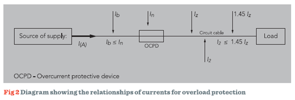
Fig 2 outlines a typical circuit, indicating the overload protective device (normally a circuit-breaker or fuse), the circuit conductors (cable) and the load.
When an overload occurs, the protective device is designed to automatically disconnect the circuit by means of the circuit-breaker tripping or fuse rupturing.
Should an overload occur in a circuit where there is no overload protection provided, the temperature of the circuit conductors is liable to increase significantly, which over time may lead to damage of insulation, joints and terminations of the conductors and/or their surroundings.
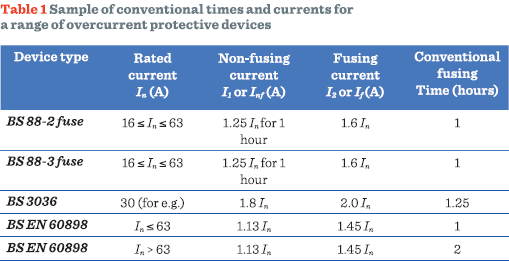
To protect against such thermal distress, any circuit design must properly coordinate the current carrying capacity of the conductors and the anticipated load current with the characteristics of the overload protective device (see Table 1).

With the exception of rewireable fuses to BS 3036, where the operating characteristics of a protective device meet the requirements of 433.1.1, as reproduced in the following expressions (i) & (ii), protection against overload will be provided:
Expression (i):
Ib ≤ In ≤ Iz
The design current of the circuit (lb) must be less than or equal to the current rating or current setting of the protective device (In), which must be less than or equal to (Iz), the lowest current-carrying capacity of the conductors forming the circuit.
Expression (ii):
l₂ ≤ 1.45Iz
The current causing effective operation of the protective device (I₂) must not exceed 1.45 times the lowest of the current carrying capacity (Iz) of any of the conductors of the circuit.
Expression (i) is self-explanatory. However, it is worthwhile considering what expression (ii) means for the designer.
Worked example
Consider a user replaceable 16 A gG fuse to BS 88-3. BS HD 60269-3 states that:- non-fusing current I1 is 1.25 In (1.25 x 16 = 20 A) for 1 hour, and
- fusing current I2 is 1.6 In (1.6 x 16 = 25.6 A).
Therefore, expression (ii) would be satisfied if, for a 16 A fuse, 1.6 In ≤ 1.45 Iz.
Using the same 16 A fuse, a short-term overload of 20 A (1.25 In x 16 A) could be sustained for 1 hour, after which time the fuse element will weaken and break. If during this process the overload was to increase to 25.6 A (1.6 In x 16 A), the fuse would rupture within the hour without causing any undue stress on the cable or associated equipment.
Additionally, where a protective device, meeting one of the standards in regulation 433.1.201 is installed, compliance with the expressions (i) and (ii) will also result in compliance with indent (iii) of regulation 433.1.1.
Location of overload protective devices
In general, and except where regulation 433.2.2 or 433.3 apply, a device for overload protection is required at the point where a reduction occurs in the current-carrying capacity of the conductors of the installation (433.2.1). If there are no outlets or spurs after the reduction in cross-sectional area, the protective device may be installed along the run of that conductor provided that:- Protection against fault current is provided (434), or
- The length of run before the overload protection device does not exceed 3 m, and the circuit is installed in a manner that reduces to a minimum the risk of:
- a fault, and
- fire or danger to persons (433.2.2).
Omission of overload protective devices
Except where a location presents a risk of fire or explosion, overload protection need not be provided:- For a conductor,
- on the load side of a point where a reduction in the value of current carrying capacity occurs if the conductor is effectively protected against overload by a protective device installed on the supply side of that point, or
- which, because of the characteristics of the load or the supply, is not likely to carry overload current.
- Where the DNO agrees that their cutout(s) provide(s) overload protection between the origin and the main distribution point of the installation (so long as overload protection is provided at that point) (433.3.1).
Summary
An overload may be considered as an overcurrent occurring in a healthy circuit resulting from overworked electrical equipment, or as a consequence of the connected load exceeding the current that the circuit was designed to carry.To prevent thermal distress and damage to the circuit conductors, the protective device is designed to automatically disconnect the circuit in the event of an overload. As such, any circuit design must properly coordinate the current-carrying capacity of the conductors and the anticipated load current with the characteristics of the overload protective device.
Electrical loads such as electric showers, immersion heaters, convector heaters and the like typically have resistive characteristics and are unable to draw more current than their current rating and are therefore unable to overload. In such cases, a device providing protection against overload need not be provided.
However, where individual loads that are inherently not liable to overload are connected to a circuit, such as a ring final circuit, that circuit can be subjected to overload.


