This article explores how designers can determine the maximum permitted Zs for both circuit-breakers and moulded case circuit-breakers (MCCBs).
In some cases, it is necessary to know the maximum permitted earth fault loop impedance (Zs) for the protective device used. This is to confirm the requirements for automatic disconnection in the event of a fault as part of the protective measure Automatic Disconnection of Supply (ADS). This article explores how designers can determine the maximum permitted Zs for both circuit-breakers and moulded case circuit-breakers (MCCBs).

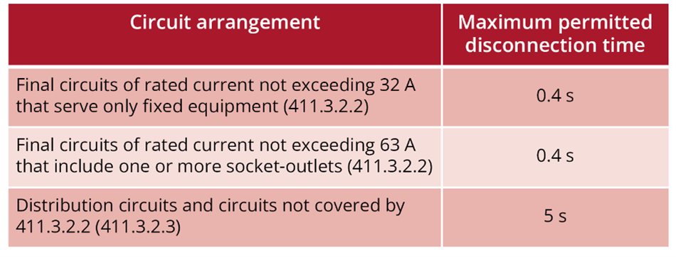
Table 1 Typical disconnection times for a TN system
“The maximum values of earth fault loop impedance to achieve the disconnection time vary with the different types of protective device and also between manufacturers. Wherever possible designers should use the manufacturer’s specific data.
Alternatively, the impedance values given in Tables 41.3 and 41.6 can be used for BS EN 60898 circuit-breakers. These values are far more onerous and in some cases may be difficult to achieve without installing larger sized cpcs.”
The designer therefore needs to understand how to determine the maximum Zs values from a manufacturer’s data for a specific protective device.
The values in Table 41.3 are obtained from the time/current characteristics curves given in Appendix 3. Formula 1 shows how this is determined.
.png)
Where:
Cmin is a correction factor to account for voltage variations. This is given as 0.95 in Appendix 3 of BS 7671.
U0 is the nominal AC rms line voltage to Earth.
Ia is the current causing operation of the device in a specified time. For a Type C circuit-breaker this is 5 x the nominal current rating of the device (In).
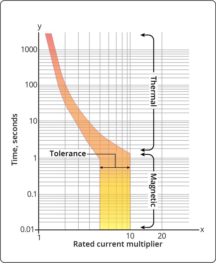
When not using the values given in Table 41.3, to obtain the value of Zs, knowledge of Ia is required. To find the value of Ia for a specific manufacturers’ device, the relevant time/current graph is required. These can be obtained from the manufacturers’ websites. Fig 1 represents a time/current curve for an imaginary Type C circuit-breaker. This graph differs slightly from that of Appendix 3, as this displays the operational tolerance of the device, and is also representative of multiple device ratings within the Type C range. This graph represents thermal-magnetic circuit-breakers, the vertical line represents the magnetic part of the device, whereas the curve represents the thermal part.

Fig 1. Time/current graph for an imaginary Type C thermal-magnetic device
To determine the value of current causing operation of the protective device (Ia), the following steps are carried out:
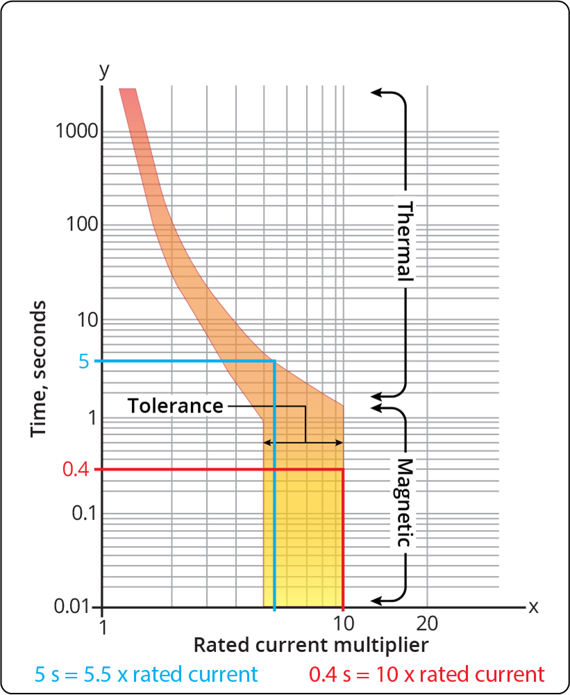
If the procedure was to be repeated for a disconnection time of 5 seconds, as indicated on Fig 2 in blue, this would yield a multiplication factor of 5.5.

Fig 2. Time/current graph for an imaginary Type C thermal-magnetic device overlaid with 0.4 s and 5 s disconnection times
If the value of operating current (Ia) to be determined is for a device such as a 45 A Type C circuit-breaker from this particular manufacturer, the following calculation should be carried out:

The values obtained for Ia can now be entered into Formula 1 to determine the maximum permitted Zs.

The maximum Zs is determined as 0.48 Ω for a disconnection time of 0.4 seconds, whereas it increases to 0.88 Ω when calculated for a disconnection time of 5 seconds.
Many MCCBs incorporate means to adjust the thermal and magnetic characteristics of the device.
The basic settings are listed below:
Ir - adjusts the Long-time current thermal setting
Isd (or Im) - adjusts Short-term magnetic setting
The Ir adjustment is manufacturer dependent, although this can be a factor of the In value, such as 0.63 - 1.0. As an example, an MCCB with an In rating of 100 A with an Ir setting of 0.8 would give an Ir of 80 A.
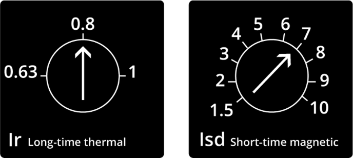
Similarly, the Isd setting can be somewhere around 1.5 – 10, which is a factor based on the In or Ir setting of the device. As an example, using the Ir value of 0.8 and an Isd setting of 7, the Isd would be 560 A (80×7=560 A). Fig 3 depicts these settings.

Fig 3 MCCB adjustments to thermal and magnetic elements of operation
Once the values have been determined by the designer, the following steps will enable the maximum Zs value for the corresponding 0.4 s and 5 s disconnection times to be obtained.
For a 0.4 s disconnection time it is not necessary to consult the graph as Isd equals Ia. However, prior knowledge of the device’s tolerance is required. For example, if the manufacturer states there is a 10 % tolerance on the device, this should be factored into the calculation as shown in Formula 4.
Note: the factor of 1.1 accounts for the 10% tolerance stated.

To obtain the operating current (Ia) for a 5 s disconnection time, the graph would be referenced. Utilising Graph 2 as the imaginary MCCB time/current curve, the value of Ia would be 440 A (5.5×80=440 A). With the current Ia obtained, the maximum permitted Zs can now be calculated as shown in Formula 5.

This article is limited to thermal-magnetic devices, although MCCBs are sometimes equipped with an electronic trip. If electronic devices are used, manufacturers’ information should be sought to obtain Ia and the corresponding maximum Zs for the devices.
Some manufacturers may provide software to aid determination of the values for their devices. This can be the most accurate and least time-consuming method for determining the maximum Zs and is essential where electronic devices are used.
Introduction
Circuit-breakers and MCCBs, manufactured to BS EN 60898 and BS EN 60947-2 respectively, are commonly used to provide automatic disconnection in the event of a fault as part of the protective measure ADS. In such cases, it is the responsibility of the designer to ensure that the protective device will operate within the permitted time. This is generally verified where the measured Zs is less than or equal to the maximum Zs permitted for the device.Disconnection times
The maximum disconnection times for ADS are contained within Chapter 41 of BS 7671. Table 1 displays the disconnection times for a TN system with a voltage to earth (U0) of 230 V AC.
Table 1 Typical disconnection times for a TN system
Finding the maximum permitted Zs of a circuit-breaker
Where a protective device to BS EN 60898 and BS EN 61009-1 is used, it is common practice to refer to Table 41.3 of BS 7671 to determine the maximum permitted Zs. However, the following statement given in Appendix 3 of BS 7671 should also be considered:“The maximum values of earth fault loop impedance to achieve the disconnection time vary with the different types of protective device and also between manufacturers. Wherever possible designers should use the manufacturer’s specific data.
Alternatively, the impedance values given in Tables 41.3 and 41.6 can be used for BS EN 60898 circuit-breakers. These values are far more onerous and in some cases may be difficult to achieve without installing larger sized cpcs.”
The designer therefore needs to understand how to determine the maximum Zs values from a manufacturer’s data for a specific protective device.
The values in Table 41.3 are obtained from the time/current characteristics curves given in Appendix 3. Formula 1 shows how this is determined.
.png)
Where:
Cmin is a correction factor to account for voltage variations. This is given as 0.95 in Appendix 3 of BS 7671.
U0 is the nominal AC rms line voltage to Earth.
Ia is the current causing operation of the device in a specified time. For a Type C circuit-breaker this is 5 x the nominal current rating of the device (In).
When not using the values given in Table 41.3, to obtain the value of Zs, knowledge of Ia is required. To find the value of Ia for a specific manufacturers’ device, the relevant time/current graph is required. These can be obtained from the manufacturers’ websites. Fig 1 represents a time/current curve for an imaginary Type C circuit-breaker. This graph differs slightly from that of Appendix 3, as this displays the operational tolerance of the device, and is also representative of multiple device ratings within the Type C range. This graph represents thermal-magnetic circuit-breakers, the vertical line represents the magnetic part of the device, whereas the curve represents the thermal part.

Fig 1. Time/current graph for an imaginary Type C thermal-magnetic device
To determine the value of current causing operation of the protective device (Ia), the following steps are carried out:
- Identify the disconnection time: Determine the required disconnection time for the device from Chapter 41 of BS 7671.
- Draw horizontal line: From the y-axis (time axis) on the graph, draw a horizontal line across the graph corresponding to the disconnection time, for example 0.4 seconds.
- Find intersection point: Locate the point where this horizontal line intersects the latter part of the time/current curve.
- Draw vertical line: Draw a vertical line from the intersection point on the curve down to the x-axis (rated current multiplier).
- Read the rated current multiplier factor: The point where the vertical line intersects the x-axis reveals the multiple to apply to the circuit-breaker rating.
If the procedure was to be repeated for a disconnection time of 5 seconds, as indicated on Fig 2 in blue, this would yield a multiplication factor of 5.5.

Fig 2. Time/current graph for an imaginary Type C thermal-magnetic device overlaid with 0.4 s and 5 s disconnection times
If the value of operating current (Ia) to be determined is for a device such as a 45 A Type C circuit-breaker from this particular manufacturer, the following calculation should be carried out:
The values obtained for Ia can now be entered into Formula 1 to determine the maximum permitted Zs.
The maximum Zs is determined as 0.48 Ω for a disconnection time of 0.4 seconds, whereas it increases to 0.88 Ω when calculated for a disconnection time of 5 seconds.
Finding the maximum Zs of an MCCB
While the previous examples given are based on circuit-breakers, the principle for obtaining Ia for a thermal-magnetic MCCB remains the same. However, there may be other settings on the device that need to be considered.Many MCCBs incorporate means to adjust the thermal and magnetic characteristics of the device.
The basic settings are listed below:
Ir - adjusts the Long-time current thermal setting
Isd (or Im) - adjusts Short-term magnetic setting
The Ir adjustment is manufacturer dependent, although this can be a factor of the In value, such as 0.63 - 1.0. As an example, an MCCB with an In rating of 100 A with an Ir setting of 0.8 would give an Ir of 80 A.
Similarly, the Isd setting can be somewhere around 1.5 – 10, which is a factor based on the In or Ir setting of the device. As an example, using the Ir value of 0.8 and an Isd setting of 7, the Isd would be 560 A (80×7=560 A). Fig 3 depicts these settings.

Fig 3 MCCB adjustments to thermal and magnetic elements of operation
Once the values have been determined by the designer, the following steps will enable the maximum Zs value for the corresponding 0.4 s and 5 s disconnection times to be obtained.
For a 0.4 s disconnection time it is not necessary to consult the graph as Isd equals Ia. However, prior knowledge of the device’s tolerance is required. For example, if the manufacturer states there is a 10 % tolerance on the device, this should be factored into the calculation as shown in Formula 4.
Note: the factor of 1.1 accounts for the 10% tolerance stated.
To obtain the operating current (Ia) for a 5 s disconnection time, the graph would be referenced. Utilising Graph 2 as the imaginary MCCB time/current curve, the value of Ia would be 440 A (5.5×80=440 A). With the current Ia obtained, the maximum permitted Zs can now be calculated as shown in Formula 5.
This article is limited to thermal-magnetic devices, although MCCBs are sometimes equipped with an electronic trip. If electronic devices are used, manufacturers’ information should be sought to obtain Ia and the corresponding maximum Zs for the devices.
Some manufacturers may provide software to aid determination of the values for their devices. This can be the most accurate and least time-consuming method for determining the maximum Zs and is essential where electronic devices are used.


