-(2).svg)
.svg)
The aim of this Apprentice Corner article is to consider how voltage, current and power are affected by parallel connected loads.

Technical Team | NICEIC
This is the final part of the series looking into resistance and connected loads. Those that have been following the series will have learnt that the resistance of a material is dependent upon:
It is also important that the correct methodology is followed when dealing with such connected loads. Parallel connected components are connected ‘across’ the supply, whilst series connected components are connected ‘in line’ or in series with the supply.
Only purely resistive loads will be considered; the effects of reactance may be discussed in a future article.
It would be useful if the Site Guide produced by Certsure was to hand when reading this article.

Unlike a series circuit, the circuit current in a parallel network can take more than one path.
Since there are multiple paths for the supply current to flow through, the current may not be the same through all the branches in the parallel network, and therefore can be classified as being a current divider – much like a series circuit could be described as being a voltage divider. The comparison between the two types of circuits is shown in Fig 2.

In Fig 2b, a shunt resistor is a component that is specifically designed to provide an alternative path for a portion of the circuit current, by having a very low resistance.
Although parallel and series circuits differ from one another, as shown by Fig 2, the equations of Ohm’s law equally apply to both types of circuit.
The total resistance for a parallel circuit cannot be found by adding together the resistances, as is the case for a series circuit; a different approach is required.
Considering Fig 1 in terms of current flow:

From Ohm’s law, the current drawn from the supply is:


Cancelling out U because the voltage is constant:

Normally, when calculating total resistance of resistors in parallel, it is easiest to use the reciprocal key on your calculator, which is typically denoted as:

Another way of determining the total resistance of a parallel circuit would be to use the product over the sum rule:

However, the formula shown above only works best when there are two resistors in parallel. Where there are more resistors connected in parallel a variant on this formula can be used, but it becomes unwieldy.
Note: The combined resistance for a parallel circuit is always less than the lowest value connected, as shown by the following example. Also, remember that the reciprocal key must be pressed after the = key in order to get the right answer using a calculator.

In a parallel circuit, since the voltage is constant, the current through each branch is dependent upon the value of resistor in that branch and can be found using the current divider rule:


Note: Power is a measure of the rate of work, and since power consumed by each load must equal the total power applied by the source(s) (as per the Law of Conservation of Energy), the manner in which the circuit is configured will have no effect on the solution process.
The power formulas identified in the third article in this series are used whether the circuit(s) are series or parallel connected.
Method 1, using the branch current and the resistance: P1 = I12 × R1
Method 2, using the branch current and the voltage dropped across a resistor: P1 = U × I1
Method 3, using the voltage dropped across a resistor and the resistance:

It is easiest to determine the branch currents first, and this can be achieved using the current divider rule:

Source voltage
U = I × R and because it is a parallel circuit having a constant voltage, either branch current and its resistance can be used.
U = I1 × R1 = 4 × 6 = 24 V
Power consumed by each branch load:
P1 = I12 × R1 = 42 × 6 = 96 W
P2 = I22 × R1 = 62 × 4 = 144 W
This can be verified by checking against the power developed at the source:
P = U × I = 24 × 10 = 240 W (96 + 144)
The 4 mm2 and 1.5 mm2 cables are protected by overcurrent protective devices to BS 88-2, rated at 32 A and 20 A respectively. The arrangement is shown in Fig 4. Is this design acceptable?

To determine if this existing heater circuit arrangement is acceptable, the design current in each parallel connected cable must be known. This arrangement can be simply modelled by a series-parallel network, which is shown in Fig 5.

The circuit current can be found from:

From Table 4D4A, the tabulated current-carrying capacity of the 4 mm2 and 1.5 mm2 cables, installed to reference method C (clipped direct) are 38 A and 21 A respectively. At first glance this appears to meet the loading requirements if the current is divided between the two branches as expected.
There are two methods that can be used to determine the current in each branch cable. One method is to use the current divider rule along with the cable resistance. To do that will require using Table B1 of Appendix B in the Site Guide to find the resistance of the 4.0 mm2 and 1.5 mm2 cables over the length of run of 30m.
This gives resistance values of: R4.0 = 0.2766 Ω and R1.5 = 0.726 Ω
Design current in the 4.0 mm2 cable:

Design current in the 1.5 mm2 cable is 52 – 37.654 = 14.35 A
Another option is to use the equation given in Appendix 10 of BS 7671.
For parallel conductors up to and including 120 mm2 cross-sectional area, the design current Ibk for conductor k is given by:

Where:
S1, S2 are the csa of the conductors, and Sk is the csa of conductor k
Current in the 4.0 mm2 cable:

Current in the 1.5 mm2 cable is 52 – 37.82 = 14.18 A
Both methods show that the current in the 4.0 mm2 cable exceeds the rating of the protective device and therefore indicates non-compliance with Regulation 433.1. Furthermore, the 32 A protective device would be able to withstand this small overload for a considerable period of time.
To appreciate why this is the case, refer to Fig 3A3(a) in BS 7671. Notice that a current of nearly 40 A does not intersect at any point on the characteristic curve for the 32 A protective device. Given that the maximum time on the vertical axis is 10,000 seconds (nearly three hours), it follows therefore that this small overload will be carried by the protective device and cable for a long period of time, probably indefinitely.
This arrangement is not acceptable and appropriate comments would be added to the Electrical Installation Condition Report.
a) Current
b) Voltage
c) Resistance
d) Power
2. Three cables, having resistances of 0.04 Ω, 0.06 Ω and 0.08 Ω respectively, are connected in parallel to carry a total load current of 160 A. What is the current carried by the cable having a resistance of 0.08 Ω? Give your answer to two significant figures.
a) 71 A
b) 53 A
c) 60 A
d) 37 A
3. The combined resistance of the circuit of MC1 is:
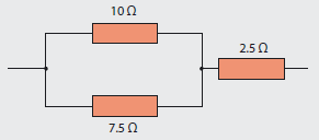.png "Fig-MC1-(Part-4).png")
Fig MC1
a) 6.8 Ω
b) 20 Ω
c) 2.7 Ω
d) 1.6 Ω
4. The combined resistance of the circuit of MC2 is 93.75 Ω. The value of resistor R is:
.png "Fig-MC2-(Part-4).png")
Fig MC2
a) 27.25 Ω
b) 18.75 Ω
c) 30 Ω
d) 125 Ω
5. The circuit arrangement of Fig 2(b) shows an ammeter having a shunt resistor connected in parallel with it. If the ammeter requires 50 mA to give full scale deflection and has an internal resistance of 20 Ω, what value of shunt resistor will be required if the ammeter is to be used to measure a current of between 0 and 5 A?
a) 0.202 Ω
b) 20 kΩ
c) 20 Ω
d) 2.0 Ω

and to press the reciprocal key once more after the = key in order to get the right answer. The method shown below is just one way of solving problems; other solution methods are equally permissible.
1. Correct option is (b)
Voltage is constant in a parallel circuit.
2. Correct option is (d)
Total resistance:

Voltage drop: U = I x RT = 160 x 0.0185 = 2.96 V
Current flow in 0.08 Ω cable:

3. Correct option is (a)

4. Correct option is (c)
Resistance of parallel branch: Rp = 93.75 - 75 = 18.75 Ω
Using:

Resistance of R:

5. Correct option is (a)
Current giving full scale deflection of the ammeter is 50 mA (Im)
Resistance of the ammeter 20 Ω (Rm)
Circuit current to be measured 5 A (I)
Shunt resistor:

The shunt resistor needs to be a very low value to ensure the bulk of the circuit current bypasses the sensitive instrument.
- The conductor material (resistivity ρ)
- its length (m),
- its cross-sectional area (m2), and
- the surrounding temperature, which is typically referred to as ambient temperature (t°C).
It is also important that the correct methodology is followed when dealing with such connected loads. Parallel connected components are connected ‘across’ the supply, whilst series connected components are connected ‘in line’ or in series with the supply.
Only purely resistive loads will be considered; the effects of reactance may be discussed in a future article.
It would be useful if the Site Guide produced by Certsure was to hand when reading this article.
Parallel connected resistors
Resistors are said to be connected together in parallel when both of their terminals are respectively connected to each terminal of the other resistor(s), as shown in Fig 1.Unlike a series circuit, the circuit current in a parallel network can take more than one path.
Since there are multiple paths for the supply current to flow through, the current may not be the same through all the branches in the parallel network, and therefore can be classified as being a current divider – much like a series circuit could be described as being a voltage divider. The comparison between the two types of circuits is shown in Fig 2.
In Fig 2b, a shunt resistor is a component that is specifically designed to provide an alternative path for a portion of the circuit current, by having a very low resistance.
Although parallel and series circuits differ from one another, as shown by Fig 2, the equations of Ohm’s law equally apply to both types of circuit.
The total resistance for a parallel circuit cannot be found by adding together the resistances, as is the case for a series circuit; a different approach is required.
Considering Fig 1 in terms of current flow:
From Ohm’s law, the current drawn from the supply is:
Cancelling out U because the voltage is constant:
Normally, when calculating total resistance of resistors in parallel, it is easiest to use the reciprocal key on your calculator, which is typically denoted as:
Another way of determining the total resistance of a parallel circuit would be to use the product over the sum rule:
However, the formula shown above only works best when there are two resistors in parallel. Where there are more resistors connected in parallel a variant on this formula can be used, but it becomes unwieldy.
Note: The combined resistance for a parallel circuit is always less than the lowest value connected, as shown by the following example. Also, remember that the reciprocal key must be pressed after the = key in order to get the right answer using a calculator.
Example 1
Resistors of 3 Ω, 5 Ω and 8 Ω are connected in parallel. What is their combined resistance?In a parallel circuit, since the voltage is constant, the current through each branch is dependent upon the value of resistor in that branch and can be found using the current divider rule:
Example 2
Consider the circuit of Fig 3, which shows two loads connected in parallel. What is the current in each branch, what is the source voltage and what is the power consumed or absorbed by each load?Note: Power is a measure of the rate of work, and since power consumed by each load must equal the total power applied by the source(s) (as per the Law of Conservation of Energy), the manner in which the circuit is configured will have no effect on the solution process.
The power formulas identified in the third article in this series are used whether the circuit(s) are series or parallel connected.
Method 1, using the branch current and the resistance: P1 = I12 × R1
Method 2, using the branch current and the voltage dropped across a resistor: P1 = U × I1
Method 3, using the voltage dropped across a resistor and the resistance:
It is easiest to determine the branch currents first, and this can be achieved using the current divider rule:
Source voltage
U = I × R and because it is a parallel circuit having a constant voltage, either branch current and its resistance can be used.
U = I1 × R1 = 4 × 6 = 24 V
Power consumed by each branch load:
P1 = I12 × R1 = 42 × 6 = 96 W
P2 = I22 × R1 = 62 × 4 = 144 W
This can be verified by checking against the power developed at the source:
P = U × I = 24 × 10 = 240 W (96 + 144)
Scenario
During a periodic inspection on a farm, you notice that a 11.96 kW heater has replaced an old unit that was supplied by a 4 mm2 steel-wired armoured cable. Instead of replacing the 4 mm2 cable for one with a larger cross-sectional area to suit the new load current requirements, a separate 1.5 mm2 armoured cable has been added and connected in parallel, as permitted by Regulation 433.4.2. The heater and its control gear are 30m from the intake position.The 4 mm2 and 1.5 mm2 cables are protected by overcurrent protective devices to BS 88-2, rated at 32 A and 20 A respectively. The arrangement is shown in Fig 4. Is this design acceptable?
To determine if this existing heater circuit arrangement is acceptable, the design current in each parallel connected cable must be known. This arrangement can be simply modelled by a series-parallel network, which is shown in Fig 5.
The circuit current can be found from:
From Table 4D4A, the tabulated current-carrying capacity of the 4 mm2 and 1.5 mm2 cables, installed to reference method C (clipped direct) are 38 A and 21 A respectively. At first glance this appears to meet the loading requirements if the current is divided between the two branches as expected.
There are two methods that can be used to determine the current in each branch cable. One method is to use the current divider rule along with the cable resistance. To do that will require using Table B1 of Appendix B in the Site Guide to find the resistance of the 4.0 mm2 and 1.5 mm2 cables over the length of run of 30m.
This gives resistance values of: R4.0 = 0.2766 Ω and R1.5 = 0.726 Ω
Design current in the 4.0 mm2 cable:
Design current in the 1.5 mm2 cable is 52 – 37.654 = 14.35 A
Another option is to use the equation given in Appendix 10 of BS 7671.
For parallel conductors up to and including 120 mm2 cross-sectional area, the design current Ibk for conductor k is given by:
Where:
S1, S2 are the csa of the conductors, and Sk is the csa of conductor k
Current in the 4.0 mm2 cable:
Current in the 1.5 mm2 cable is 52 – 37.82 = 14.18 A
Both methods show that the current in the 4.0 mm2 cable exceeds the rating of the protective device and therefore indicates non-compliance with Regulation 433.1. Furthermore, the 32 A protective device would be able to withstand this small overload for a considerable period of time.
To appreciate why this is the case, refer to Fig 3A3(a) in BS 7671. Notice that a current of nearly 40 A does not intersect at any point on the characteristic curve for the 32 A protective device. Given that the maximum time on the vertical axis is 10,000 seconds (nearly three hours), it follows therefore that this small overload will be carried by the protective device and cable for a long period of time, probably indefinitely.
This arrangement is not acceptable and appropriate comments would be added to the Electrical Installation Condition Report.
Summary
This series on resistance will have shown that having knowledge of how currents and voltages behave in series and parallel resistor networks, provides the tools to solve real life problems.Multiple-choice questions
1. The element that is constant in a parallel circuit is:a) Current
b) Voltage
c) Resistance
d) Power
2. Three cables, having resistances of 0.04 Ω, 0.06 Ω and 0.08 Ω respectively, are connected in parallel to carry a total load current of 160 A. What is the current carried by the cable having a resistance of 0.08 Ω? Give your answer to two significant figures.
a) 71 A
b) 53 A
c) 60 A
d) 37 A
3. The combined resistance of the circuit of MC1 is:
Fig MC1
a) 6.8 Ω
b) 20 Ω
c) 2.7 Ω
d) 1.6 Ω
4. The combined resistance of the circuit of MC2 is 93.75 Ω. The value of resistor R is:
Fig MC2
a) 27.25 Ω
b) 18.75 Ω
c) 30 Ω
d) 125 Ω
5. The circuit arrangement of Fig 2(b) shows an ammeter having a shunt resistor connected in parallel with it. If the ammeter requires 50 mA to give full scale deflection and has an internal resistance of 20 Ω, what value of shunt resistor will be required if the ammeter is to be used to measure a current of between 0 and 5 A?
a) 0.202 Ω
b) 20 kΩ
c) 20 Ω
d) 2.0 Ω
Apprentice Corner answers
Remember to use the reciprocal key on your calculator which is typically:and to press the reciprocal key once more after the = key in order to get the right answer. The method shown below is just one way of solving problems; other solution methods are equally permissible.
1. Correct option is (b)
Voltage is constant in a parallel circuit.
2. Correct option is (d)
Total resistance:
Voltage drop: U = I x RT = 160 x 0.0185 = 2.96 V
Current flow in 0.08 Ω cable:
3. Correct option is (a)
4. Correct option is (c)
Resistance of parallel branch: Rp = 93.75 - 75 = 18.75 Ω
Using:
Resistance of R:
5. Correct option is (a)
Current giving full scale deflection of the ammeter is 50 mA (Im)
Resistance of the ammeter 20 Ω (Rm)
Circuit current to be measured 5 A (I)
Shunt resistor:
The shunt resistor needs to be a very low value to ensure the bulk of the circuit current bypasses the sensitive instrument.


